User Guide#
This guide explains how to launch MagScope and use its interface. If you have not already read the Getting Started.
Launching the Demo Graphical User Interface (GUI)#
MagScope includes a simulated camera so the interface can be explored without laboratory hardware. Launch the demo from a Python interpreter by running:
import magscope

scope = magscope.MagScope()
scope.start()
This creates the default window layout and begins streaming data from the built-in demo pipeline.
You can only launch MagScope once.
After launching it if you want to start again you must close it and delete the instance (delete scope in the example).
To close MagScope, close the main MagScope window; shutdown might take up to a couple of minutes.
Alternatively, call MagScope.stop.
Windows and Multiple Screens#
It is often easier to see everything in MagScope with multiple screens. MagScope opens one main window with dockable Live Camera and Live Plots panes. You can undock either pane and move it to another screen, then dock it again by dragging it back into the main window. Use the Layout menu to show hidden viewer panes, dock all floating panes, or reset the viewer layout.
Live Video Viewer#
MagScope automatically launches with a live video feed. You can zoom by scrolling in and out with a mouse wheel.
Control Panels#
Panels for each set of controls can be hidden or revealed by clicking on the panel’s title.
Panels can move arranged by dragging them by the top-right corner. If space permits a new column can be added.
The control panels can be reset to their default arrangement from Preferences by opening the
Appearance/Layout tab and clicking Reset GUI Layout.
Finding Controls#
Use the Search for controls ... box in the top menu bar to find controls without running them.
Search suggestions appear while you type; press Enter or select a suggestion to show where that
control is located. MagScope opens the relevant panel, menu, or Preferences tab, scrolls the control
into view when needed, and temporarily highlights it. Search is guide-only: it does not click buttons,
change settings, or execute actions.
Useful examples include:
ROI- opensPreferencesand highlights the ROI size setting in theMagScopetab.find beads- showsAuto Bead Selectionin theBead Selectionpanel.FFT rmin- opensPreferencesand highlights the tracking option in theTrackingtab.dock- opens theLayoutmenu and highlightsDock All Windowswithout docking anything.
Press Ctrl+K or Ctrl+F to focus the search box. Press Escape while the search box is
focused to clear it.
Bead Selection#
Instructions and some controls for selecting bead ROIs can be found in the “Bead Selection” panel. To add a bead ROI click on the live video feed. A bead ROI will be created centered on your cursor. You can move the ROI by dragging the ROI. You can remove a bead by right-clicking the ROI.
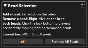
Each bead ROI will be assigned an ID number in the corner of the ROI. The ID number always increases to prevent mixing up beads.
To clear all beads and reset the ID number count to 0 click the “Remove All Beads” button in the “Bead Selection” panel.
You can also click Auto Bead Selection to freeze one recent live image, choose a seed bead, and preview matching bead ROIs before adding them. The dialog shows the frozen image, the current bead ROIs, a score threshold control for the proposed matches, and the match score next to each proposed ROI. Click Accept Proposed Beads to add the visible proposals through the normal bead creation path, or Cancel to leave the confirmed bead list unchanged.
During an experiment you may want to lock the beads so you do not accidentally add/move/remove any of the ROIs. You can do this by click the 🔓 button on the “Bead Selection” panel. This will only affect user interactions (it will not effect the XY-Lock). You can click the button again to unlock.
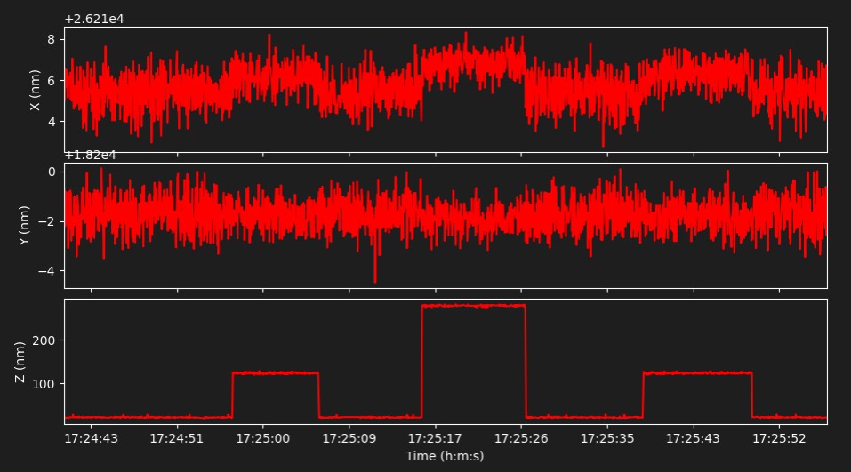
Live Plots#
MagScope provides a live plot of bead track. You can also add a live view of data from hardware such as motor positions or calibrated force. See the Connect Your Hardware guide for details.
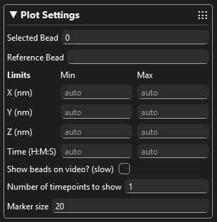
You can set limits on any axis using the min and max limits in the “Plot Settings” panel. By default the min and max values are automatically calculated. Times should be specified with a 24-hour clock. Such as “14:20:45” for 14 hours, 20 minutes, and 45 seconds. Or “14.12.45” will work the same. Or “14” for 14 hours, 0 minutes, and 0 seconds.
You can control which bead is plotted and which bead is selected with the “Plot Settings” panel. You can also set a reference bead who values will be subtracted from the other beads. Changing the plot setting does not affect how any of the data is saved. The raw tracks are always saved.
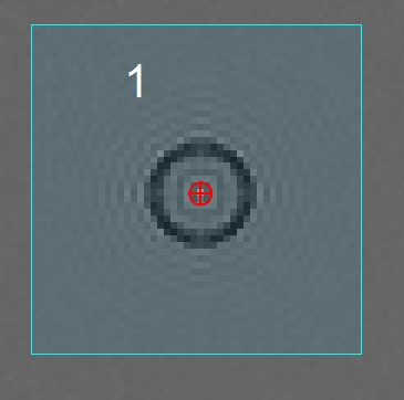
The selected bead’s ROI will be highlighted in red. The reference bead’s ROI will be highlighted in green. All other bead ROIs will be highlighted in blue.
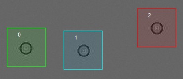
There are also some options for plotting the xy position of the beads on the live video feed in a crosshair 𐀏. This can be useful for debugging but can slow down the user interface and should not be left enabled in general.
Status Panel#
The status panel provides information on the status of the GUI, video processing, and video buffer.
The “Display Rate” is not the camera’s framerate but instead the rate at which the live video feed is being updated. It is normal for the display rate to be slower than your cameras framerate. The video feed will be processed at the full framerate.
The number of video processor should always be at least 3 and there is little benefit to increasing them. If all processor are constantly in use (for example “3/3”) then you may have selected too many beads and the processors can not keep up.
The video buffer size can be adjusted from the MagScope Settings panel, and settings persist automatically between launches.
The video buffer should ideally never fill all the way up. If it does fill up it will be purged. Purges result in those frames being deleted with out being processed. If the buffer is filling all the way up and purging then you may have selected too many beads. Optimizing the video buffer size settings may allow you to process more beads. Settings can also be imported from or exported to YAML files when needed.
Camera Settings#
Camera settings will depend on the camera you are using. By default the program starts with a simulated camera. With the simulated camera you can change the framerate, number of beads simulated, and other simulation settings. To check the current value of the camera setting you will need to click the refresh button in the bottom-left. When adding you own camera these setting will be controlled by what settings you provide access to in your camera class. See the Connect Your Camera guide for more details.
Acquisition (Saving Data)#
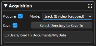
The “Acquire” checkbox enables data processing in general. If this is disabled no video will be sent for processing. These is almost never a reason to disable this.
The “Save” checkbox enabled saving data to the disk. The data will be saved to the directory selected with the “Select Directory to Save To” button. If no directory is selected then no data is saved.
Several types of data can be saved: tracks, full field-of-view videos, and cropped videos. Tracks are saved as text files with the data and time in the name. Each batch of video processed is saved as one file. This can result in a lot of files. But these can be combined later with a simple Python script. Videos are saved as tiff files which can be opened in ImageJ. Saving video files can be very slow and can result in the video buffer filling up and needing to be purged resulting in lost data. In general only the tracks should be saved. Any combination of tracks and/or video can be selected with the “Mode” selector.
Histogram#
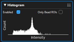
The histogram panel provide a simple intensity histogram of the live video feed. It may slow down the user interface so its best to not leave this enabled all the time. You can select for the histogram to either use the entier camera’s field-of-view or be limited to just the bead ROIs.
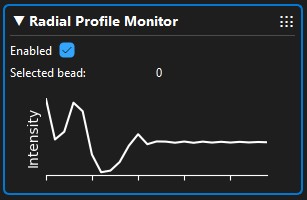
Radial Profile Monitor#
The radial profile monitor can provide a live view of one bead’s radial profile. This is particularly helpful for optimizing radial profile settings and debugging. The currently selected bead (see Plot Settings) will be used. This can slow down the user interface so its best to not leave this enabled all the time.
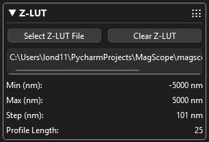
Z-LUT#
The “Z-LUT” panel allows you to load in previously generated Z-LUTs. It also provides basic information about the current Z-LUT.
XY-Lock#
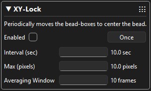
Once: Keeping your beads in the center of the ROI improves tracking accuracy. It can be annoying to move each bead to the center of the ROI. When a bead is being tracked MagScope can move the ROI so that the bead is in the exact center. Just open the XY-Lock panel and click the “Once” button.
Automatic: When you are running a long experiment you might notice some drift in your stage/sample over time. You can have MagScope periodically run the centering routine by checking the “Enabled” checkbox. You can control the frequency of updates and set a maximum distance to move at a time.
The bead XY-positions are relative to the top-left of the camera’s field of view. Therefore, moving the ROI does not affect the bead’s detected position, unless it is near the edge of the ROI. Generally you should not see any “jumps” in the beads position when using the XY-Lock.
XY-Lock has three settings:
Interval - The frequency at which the ROI will move in an attempt to center the bead.
Max - An upper limit you can set. The ROI will not move more than this amount of pixels at a given time. If the XY-Lock is overcorrecting for bead motion try decreasing this value.
Averaging Window - Sets how many of the latest valid bead positions are averaged together before calculating where the ROI should move to.
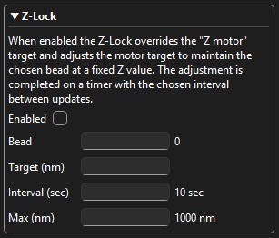
Z-Lock#
Z-Lock seems similar to XY-Lock but works a little different. Z-Lock takes control of the piezo “Z” or “focusing” motor to keep one bead at a specific Z value. You must have a Z-LUT loaded and the selected bead’s current focus must be within the range of the Z-LUT. You must have your piezo motor controlled by MagScope to use this feature. Connecting hardware is covered in the Connect Your Hardware guide.
Z-Lock has five settings which must be set before the Z-Lock will take affect:
Enabled - Whether the Z-Lock is active.
Bead - Which bead ROI will be kept in focus. This should generally be a reference bead.
Target - The Z-value that the selected bead will be maintained at.
Interval - The frequency with which the difference between the target value and current value will be checked/adjusted.
Max - An upper limit you can set. The Z-Lock caps each correction at this amount, then applies damping so the motor moves half of the capped correction. If the Z-Lock keeps overshooting the target, try decreasing this value.
Scripting#
To learn how to use scripts to automate tasks in MagScope read the Scripting guide.